 +86-13752771911
 E-mail:ptfetube@yozonetech.cn




PTFE FEP Dual Wall vs Single Wall Heat Shrink Defining the Required Function
November 14, 2026
Yozonetech
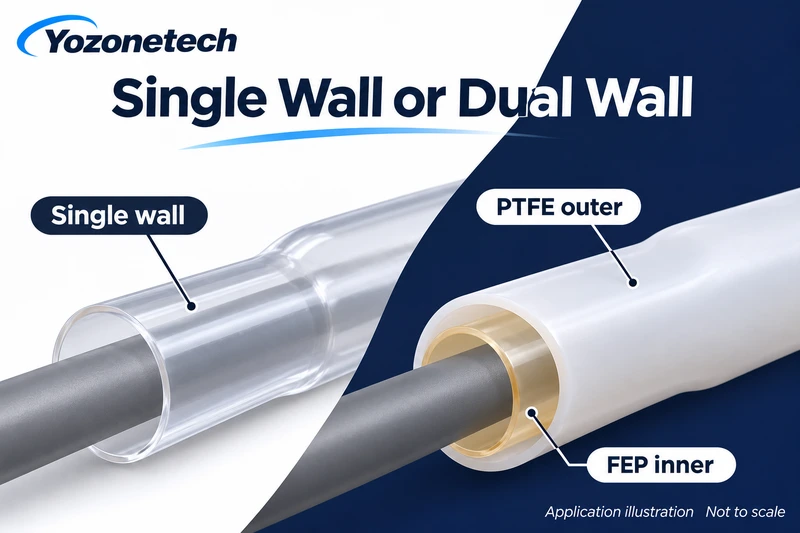
Application illustration. Not a customer photograph, test result or assembly rating.
Choose PTFE and FEP dual wall heat shrink tubing when the project needs a shrinking outer jacket plus an inner material that can flow around the component. Consider single wall FEP heat shrink tubing or single wall PTFE heat shrink tubing when a contracting sleeve is the required construction. The choice starts with the assembly function, installation limits and acceptance criteria.
State the required function first
Write whether the sleeve must provide insulation, surface protection, contour coverage or encapsulation. If the requirement includes moisture exclusion, define the exposure and the permitted leakage or ingress criterion. “Waterproof heat shrink” is not a complete specification.
Define what must remain accessible after installation. A component intended for later inspection or replacement needs a different service plan from a permanently encapsulated connection. Ask the equipment designer how the sleeve will be removed and how the part will be inspected if rework becomes necessary.
Understand the layer arrangement
In the PTFE outer and FEP inner construction, the jacket recovers while the liner melts and flows. Single wall sleeves do not include that separate melt-fill layer. This general mechanism is also described in the independent Zeus bilayer heat shrink reference; its branded ratings and approvals are not Yozonetech specifications.
For Yozonetech’s offered construction and quotation details, use the PTFE and FEP dual wall product page and request the selected size drawing. Do not substitute a wall or temperature value from another manufacturer’s grade. Polymer identity does not establish a qualified finished assembly.
| Project need | Single wall review | PTFE outer and FEP inner review |
| Cover a component | Check fit and coverage | Decide whether liner filling is needed |
| Fill around contours | No separate melt-fill liner | Check liner quantity and access to contours |
| Limit installation heat | Confirm the selected sleeve process | Confirm jacket recovery and liner flow together |
| Meet an ingress requirement | Validate the complete interface | Validate fill and all entry paths |
| Keep service access | Define removal method | Assess consequences of encapsulation |
Check the installation envelope
Measure the largest obstruction that the expanded sleeve must pass over and the smallest region requiring contact. Include tolerance, connector shoulders and overlaps. Confirm minimum supplied ID rather than choosing solely from a nominal shrink ratio. Specify covered length and the allowable finished outside envelope.
For dual wall candidates, include contours, cavities and cable exits in the drawing. Ask how the liner volume and finished dimensions will be assessed. Free-recovery wall data describe a different measurement condition from the wall installed on a component. Approve the installed geometry through a representative trial.
Establish a process the component can tolerate
Check installation heat limits for the actual component and its solder, insulation, adhesives and coatings. Obtain instructions for the selected sleeve and equipment. A heater setting does not demonstrate the temperature reached by the assembly. Instrument the trial where needed and record the process used.
Do not choose PTFE outer dual wall purely from the service-temperature capability associated with PTFE resin. Installation and service conditions are separate requirements. The relevant limits are those of the complete assembly and the specific offered construction. If heat exposure cannot be accepted, review another construction or protection method with engineering before purchase.
Define evidence for the finished part
Prepare an inspection plan before the trial. It should identify covered length, visible damage, acceptable liner displacement, functional access and any electrical or environmental checks needed by the project. Agree inspection locations and acceptance limits rather than relying on a smooth external appearance.
For immersion or pressure exposure, define the fluid, temperature, pressure and duration with the responsible engineer. Assess wire exits and other interfaces as well as the sleeve surface. Heat shrink is not a pressure hose; material temperature capability is not a pressure rating. Record what was tested and avoid extending the result to other sizes or constructions without review.
Compare candidates on one drawing
Application demonstration, not a customer case: an equipment team considers a sleeve for a sensor connection. It first separates simple coverage from a defined encapsulation requirement, then checks installation heat limits. Candidate single wall and dual wall samples are assessed against the same drawing and inspection plan. No customer, successful test or performance improvement is assumed.
Request a function based sample
Send Yozonetech the component drawing, maximum and minimum diameters, covered length, operating environment, installation heat limits and quantity. Include any ingress, electrical or inspection criteria. Our engineers can help clarify open requirements and suggest a candidate for your approval.
Yozonetech offers heat shrink tubing with a minimum order of 100 m for small sizes and 50 m for larger sizes; confirm the size boundary and selected construction in the quotation. Samples are free with courier charges collected from the recipient. Routine preparation is typically 3–5 days subject to specification and stock confirmation; custom production and transport are agreed separately. Custom dimensions can be reviewed. EXW, FOB, CIF and DDP can be discussed for the destination and route. Request documents applicable to the supplied product and intended use.
Contact Yozonetech: ptfetube@yozonetech.cn | https://www.chinaptfetube.com/