 +86-13752771911
 E-mail:ptfetube@yozonetech.cn



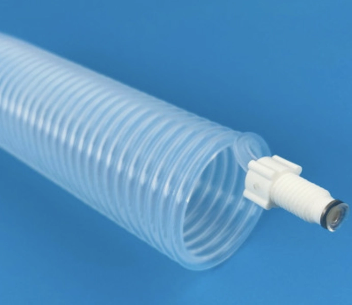
PTFE Spring Tubing
Product Overview
Coiled fluoropolymer tubing with straight ends and FEP or PFA material options
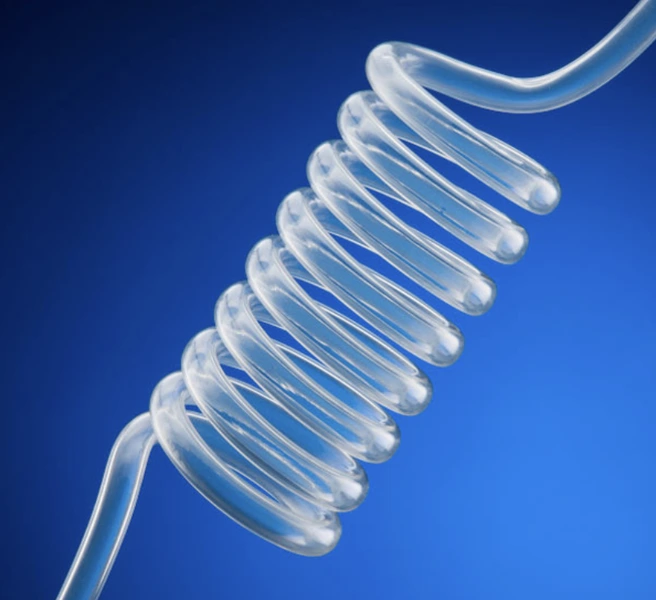
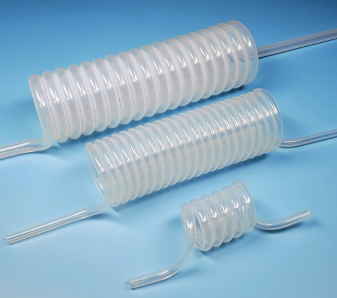
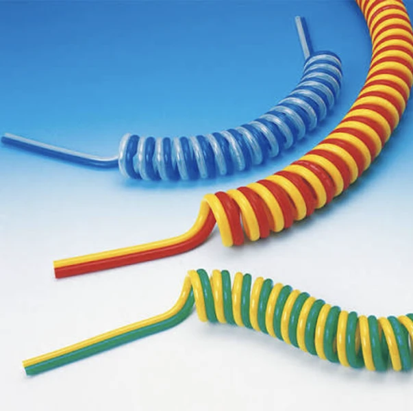
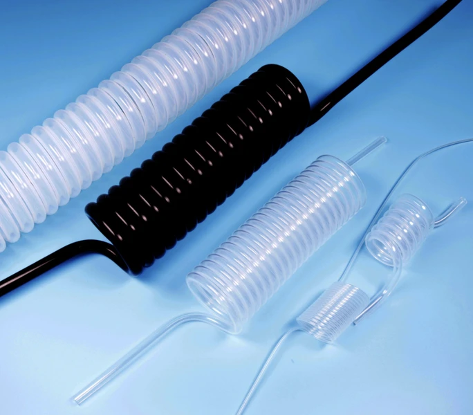
Yozonetech supplies spring-shaped fluoropolymer tubing for equipment connections that require a compact coiled form and an extended operating reach. The tube is formed into a helical coil with straight sections at both ends for connection to the equipment.
Choose PTFE, FEP or PFA against the application requirements. The complete size tables below provide 20 configurations across seven metric and inch-designated tube sizes, with operating-distance options and separate coil and tube dimensions.
Send the required tube size, material, operating distance and quantity to ptfetube@yozonetech.cn for a quotation.
Product Benefits
Coiled construction
The spring form provides a compact tubing arrangement with an operating reach suited to equipment layout. Select the coil geometry, end lengths and movement requirements together; the listed reach does not establish a fatigue-life rating.
Chemical resistance
Fluoropolymer material options provide corrosion resistance and resistance to many acids and alkalis. Confirm compatibility with the exact medium, concentration and exposure conditions.
Thermal and aging resistance
The material range offers high- and low-temperature resistance and resistance to aging. Confirm the temperature limit of the finished tube for the selected material, geometry, pressure and connection system.
Insulation and nonstick surface
Fluoropolymer tubing offers electrical insulation and a nonstick surface. Agree any electrical, surface or cleanliness requirements for the selected construction.
Technical Overview
| Parameter | Specification |
| Material options | PTFE, FEP and PFA |
| Product form | Helically coiled tube with straight end sections |
| Complete configurations | 20 entries across seven tube-size groups |
| Listed operating distance | 0.5-3 m across the complete range; combinations shown below |
| Straight end lengths | 80 mm at each end for every listed configuration |
| Coil length C | 188-533 mm across the tables |
| Product total length L | 348-693 mm across the tables |
| Coil dimensions | ID D and OD F are separate from tube ID O and OD P |
| Pressure and temperature limits | Confirm for the exact material, size and assembly |
Metric Spring Tube Specifications
Metric size labels are tube ID × OD in mm. Reach is the listed operating distance in m. All dimensional columns except Base len. are in mm. End 1 and End 2 are the straight connection sections; C is the coiled-section length and L is the overall product length.
| Size | Reach m |
Base len.* |
Turns | End 1 mm |
End 2 mm |
Coil C mm |
Total L mm |
Coil ID D mm |
Coil OD F mm |
Tube ID O mm |
Tube OD P mm |
| 2 × 4 | 0.5-1 | 6 | 47 | 80 | 80 | 188 | 348 | 35 | 43 | 2 | 4 |
| 2 × 4 | 1-1.5 | 9 | 72 | 80 | 80 | 288 | 448 | 35 | 43 | 2 | 4 |
| 2 × 4 | 1.5-2.5 | 12 | 96 | 80 | 80 | 384 | 544 | 35 | 43 | 2 | 4 |
| 4 × 6 | 0.5-1 | 6 | 36 | 80 | 80 | 216 | 376 | 45 | 57 | 4 | 6 |
| 4 × 6 | 1-1.5 | 9 | 55 | 80 | 80 | 330 | 490 | 45 | 57 | 4 | 6 |
| 4 × 6 | 1.5-2.5 | 12 | 74 | 80 | 80 | 444 | 604 | 45 | 57 | 4 | 6 |
| 6 × 8 | 0.5-1 | 6 | 26 | 80 | 80 | 208 | 368 | 63 | 79 | 6 | 8 |
| 6 × 8 | 1-1.5 | 9 | 39 | 80 | 80 | 312 | 472 | 63 | 79 | 6 | 8 |
| 9 × 12 | 0.5-1 | 6 | 19 | 80 | 80 | 228 | 388 | 76 | 100 | 9 | 12 |
| 9 × 12 | 1-1.5 | 9 | 29 | 80 | 80 | 348 | 508 | 76 | 100 | 9 | 12 |
| 9 × 12 | 1.5-2.5 | 12 | 39 | 80 | 80 | 468 | 628 | 76 | 100 | 9 | 12 |
* Base len. reproduces the base-tube total-length values 6, 9 and 12. The unit is not stated in the table and must be confirmed with the production specification. These values are distinct from the overall formed product length L.
Understand the Dimensions
| Symbol | Meaning |
| A | First straight end length in the dimensional diagram |
| B | Second straight end length in the dimensional diagram |
| C | Axial length of the coiled section |
| L | Overall axial product length including both straight ends |
| D | Coil inner diameter |
| F | Coil outer diameter |
| O | Tube inner diameter |
| P | Tube outer diameter |
For every listed configuration, the two straight sections are 80 mm each and L = C + 160 mm. The source table labels both straight sections B; End 1 and End 2 above distinguish them, following the A and B arrangement shown in the diagram.
The 6 × 8 mm size has two listed operating-distance options. No third configuration has been assumed. Other sizes and coil arrangements can be reviewed against a drawing.
Inch Designated Spring Tube Specifications
Size is the nominal inch designation. All tube and coil diameters in the table are in mm. The paired catalog dimensions use OD × ID: 1/8 = 3.2 × 1.6 mm; 1/4 = 6.35 × 4.35 mm; 1/2 = 12.7 × 9.53 mm. The tube ID and OD columns state each dimension separately.
| Size | Reach m |
Base len.* |
Turns | End 1 mm |
End 2 mm |
Coil C mm |
Total L mm |
Coil ID D mm |
Coil OD F mm |
Tube ID O mm |
Tube OD P mm |
| 1/8 | 1-1.5 | 6 | 80 | 80 | 80 | 256 | 416 | 20 | 26.4 | 1.6 | 3.2 |
| 1/8 | 1.5-3 | 9 | 121 | 80 | 80 | 378 | 538 | 20 | 26.4 | 1.6 | 3.2 |
| 1/8 | 2.5-3 | 12 | 162 | 80 | 80 | 518 | 678 | 20 | 26.4 | 1.6 | 3.2 |
| 1/4 | 0.5-1 | 6 | 36 | 80 | 80 | 229 | 389 | 45 | 57.7 | 4.35 | 6.35 |
| 1/4 | 1-1.5 | 9 | 55 | 80 | 80 | 349 | 509 | 45 | 57.7 | 4.35 | 6.35 |
| 1/4 | 1.5-2.5 | 12 | 73 | 80 | 80 | 464 | 624 | 45 | 57.7 | 4.35 | 6.35 |
| 1/2 | 0.5-1 | 6 | 21 | 80 | 80 | 267 | 427 | 76 | 101.4 | 9.53 | 12.7 |
| 1/2 | 1-1.5 | 9 | 32 | 80 | 80 | 406 | 566 | 76 | 101.4 | 9.53 | 12.7 |
| 1/2 | 1.5-2.5 | 12 | 42 | 80 | 80 | 533 | 693 | 76 | 101.4 | 9.53 | 12.7 |
* Base len. values retain the unlabelled source unit and require confirmation. The 1/8 inch operating-distance intervals are preserved as 1-1.5 m, 1.5-3 m and 2.5-3 m, including their overlap.
Select the Coil and Material
Start with the required tube bore and connection outside diameter, then review coil ID and OD, number of turns, formed length and operating distance. Provide clearance requirements, routing and the direction and extent of movement. Avoid selecting by coil diameter alone.
PTFE, FEP and PFA are the listed material options. Confirm which dimensions are available in the selected material, together with resin grade, color, tolerances and connection details. A catalog configuration is not a guarantee of stock availability in every material.
Operating Conditions
Specify the medium, concentration, working pressure or vacuum, normal and maximum temperature and movement cycle requirements. Pressure, burst strength, minimum bend radius, permitted extension and cyclic life must be confirmed for the exact tube and assembly.
Support the straight ends and arrange the coil so that movement does not create torsion, sharp bends at the connection or contact with abrasive edges. The permitted service conditions depend on the whole assembly, including fittings and seals.
Typical Applications
Pharmaceutical and medical equipment
Equipment fluid connections where chemical compatibility, routing and a coiled tube form are useful. Define cleanliness, extractables and required material or product documentation for the specific use.
Electronics and semiconductor equipment
Compact connections in electronic and semiconductor equipment. Specify purity requirements, dimensional clearance and any inspection or electrical requirements.
Mechanical equipment
Connections that require a coiled arrangement and a defined operating reach. Review displacement, frequency, routing and support with the equipment design.
Food processing
Equipment fluid paths where the selected material and finished tube meet the process and contact requirements. Specify the required compliance documentation and cleaning conditions.
Chemical and aerospace equipment
Coiled fluid connections for demanding equipment environments. Confirm fluid compatibility, temperature, pressure, mechanical duty and application-specific qualification.
Custom Spring Tubing
Send a drawing specifying material, tube ID O and OD P, coil ID D and OD F, turns, coil length C, overall length L and straight ends A and B. Include required operating distance, end orientation, connection type, quantity and dimensional tolerances.
Agree an inspection plan for tube dimensions, coil geometry, end lengths, surface condition and any leak, pressure, cleanliness or movement testing. Custom sizes and operating-distance options can be reviewed with your inquiry.
Frequently Asked Questions
Is the coil diameter the same as the tube diameter
No. D and F describe the coil envelope, while O and P describe the hollow tube itself. Specify both sets of dimensions.
Which materials are available
The range includes PTFE, FEP and PFA options. Confirm size availability and the permitted service conditions for the selected material and assembly.
What does operating distance mean
It is the listed reach range for the selected configuration, expressed in meters. It is separate from the formed product length L and does not establish an unlimited extension or cycle-life rating.
Can I change the end lengths or coil dimensions
Custom requirements can be reviewed against your drawing. The common tables use 80 mm at each straight end; include any different end lengths and connection requirements in your inquiry.
Request a Spring Tubing Quote
Send the selected size and operating distance, material, quantity, end connections and service conditions. For a custom coil, include the full dimensional drawing, tolerances and required inspection or documentation.
Email: ptfetube@yozonetech.cn
WhatsApp / Tel / WeChat: +86 13752771911
Website: www.chinaptfetube.com