 +86-13752771911
 E-mail:ptfetube@yozonetech.cn




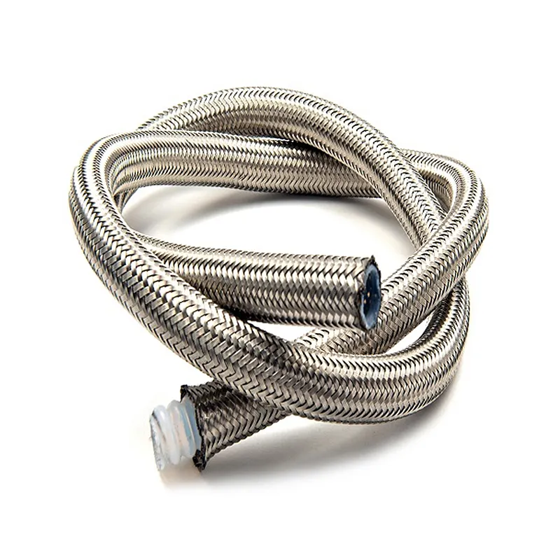


PTFE SS304/316 Geflechtschlauch SAE100R14 für Industrie und Lebensmittelbereich
Product Overview
Smooth bore and convoluted PTFE hose with stainless steel and polymer fiber reinforcement
Yozonetech supplies PTFE braided hose for industrial fluid transfer, chemical handling and hydraulic connections. Choose a smooth-bore liner for a clear flow path or a convoluted liner for more flexible routing. Liner options include conventional PTFE, imported PTFE resin and carbon-black-filled conductive PTFE. Reinforcement options include 304 and 316L stainless steel wire, polyester yarn and Kevlar aramid fiber.
We can produce two- and three-layer braided constructions, including combinations of stainless steel and polymer fiber layers. Each configuration is matched to the required pressure, temperature, routing and end connections. Send your application details or drawing to request a quotation.
Testing and Inspection
A hose inspection plan can cover liner integrity, dimensional control, pressure performance and material properties. Specify the tests and acceptance criteria required for your order. Equipment capacity, test method and reporting requirements are confirmed with the selected supply configuration.
Automatic pneumatic leak testing
PTFE inner tubes can be checked for leakage using automatic air-pressure testing with a 60-second pressure hold. The test pressure must be stated in a defined unit and agreed for the liner being supplied.
Strong light inspection
Monochromatic and combined light sources help reveal black particles, paraffin and other visible contamination in the PTFE liner.
Laser dimensional control
Laser diameter measurement supports dimensional monitoring during liner production. Inner diameter, outer diameter and wall acceptance limits are defined in the inspection plan.
Spark testing
Electrical spark testing screens the PTFE liner for pinholes and small defects. Agree test voltage and method for the liner wall and construction.
Hydrostatic and burst pressure testing
Hydrostatic equipment evaluates braided hose pressure integrity, with proof-test criteria specified for the selected hose. Burst testing evaluates ultimate pressure performance; the reference burst-test bench has a maximum capacity of 200 MPa, which is an equipment limit rather than a hose rating.
Temperature impulse and flex testing
High-temperature impulse testing evaluates pressure cycling at media temperatures up to +260°C in the reference setup. A temperature-controlled bending test bench provides environmental conditions from -60°C to +300°C. These equipment ranges do not define the operating limits of the finished hose.
Tensile and electrical tests
Tensile testing measures PTFE liner strength and elongation, with D638 identified as a reference method. Electrical breakdown testing evaluates liner insulation. Test standards, specimen preparation and acceptance limits are agreed for the applicable product.
Liner and Reinforcement Options
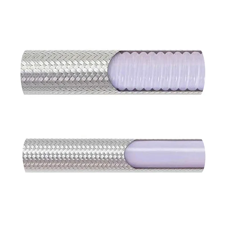
Smooth bore PTFE liner
A milky-white PTFE liner with a smooth internal surface provides a clear flow path for fluid transfer. The R-series reference construction uses one reinforcing layer of 304 stainless steel wire. The smooth-bore reference is not recommended for dynamic applications; specify motion and pressure cycling separately when selecting the finished assembly.
Convoluted PTFE liner
A milky-white PTFE liner with an internally corrugated profile provides greater routing flexibility and a smaller bend radius. The R-series reference uses one reinforcing layer of 304 stainless steel wire and identifies this construction for dynamic use. Repeated flexing still requires confirmation of bend radius, displacement, cycle rate and service life.
304 and 316L stainless steel braid
Choose 304 or 316L stainless steel wire reinforcement according to the installation environment and required construction. Specify external exposure, corrosion concerns and fitting materials together with the fluid-side requirements.
Polyester and Kevlar braid
Polyester yarn and Kevlar aramid fiber are available as polymer reinforcement options. Select the fiber against the required temperature, mechanical duty and external exposure; the PTFE liner temperature range does not automatically apply to every polymer braid.
Two and three layer mixed braiding
We can braid two or three layers using stainless steel wire, polymer fiber yarn or a combination of both. Specify the reinforcement materials and layer arrangement for review. Pressure ratings, bend behavior, outside diameter and end-fitting retention must be established for each finished construction; adding layers does not create a universal pressure rating.
Imported PTFE resin options
Imported PTFE resin options include Japanese Daikin 302 dispersion resin as identified for the imported-material constructions. Smooth-bore, convoluted, thick-wall and smooth-inside corrugated-outside forms can be specified. Confirm the resin manufacturer, exact grade and traceability requirements in the order specification.
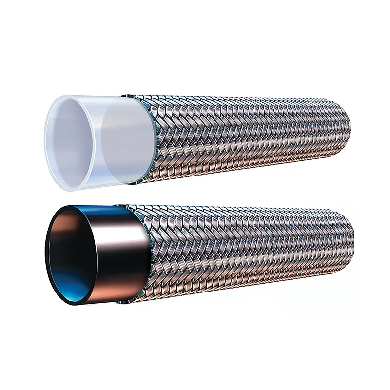
Carbon black conductive PTFE liners
Carbon-black-filled PTFE is available for applications requiring a conductive fluid-contact liner. Options include a black liner and a composite liner with a blue exterior and black conductive inner layer. Specify the required electrical resistance, test method and grounding arrangement for the complete assembly. A conductive liner does not by itself establish a hazardous-area approval.
Smooth inside corrugated outside liners
This construction combines a smooth fluid-contact bore with an externally corrugated profile, with unbraided and stainless-steel-reinforced reference versions. The smooth bore avoids internal corrugation pockets; drainage and residue behavior still depend on routing, fluid and cleaning conditions.
Product Benefits
- PTFE fluid-contact liner for a broad range of hydraulic fluids and chemicals, subject to compatibility review for the actual medium and concentration.
- Smooth-bore and convoluted options to match flow-path and routing requirements.
- Stainless steel and polymer fiber reinforcement choices for application-specific assemblies.
- Two- and three-layer construction, including metal and fiber combinations.
- Inspection and test requirements tailored to the agreed hose specification.
Technical Parameters
Temperaturbereich
The reference PTFE hose families share a listed temperature range of -50°C to +260°C. The permitted range of a supplied assembly depends on liner grade, braid materials, layer arrangement, fittings, seals, pressure and service conditions. Polymer-braided and mixed constructions require their own confirmed limits.
Pressure reduction for conventional conductive and high pressure constructions
For R, G, B, O and Z reference families, the pressure factors are 0.75 at 170°C, 0.65 at 180°C and 0.40 at 205°C. Permitted working pressure = the selected hose base working pressure × the applicable temperature factor. These values apply only to the corresponding confirmed construction.
Pressure reduction for imported W and Y constructions
The imported-resin W and Y reference families use factors of 0.85 at 170°C, 0.75 at 180°C and 0.50 at 205°C. These factors must not be transferred to other imported-resin products: the imported ultra-high-pressure O version and Z family retain the 0.75, 0.65 and 0.40 factors. Confirm factors at all other temperatures rather than extrapolating to +260°C.
Static and dynamic selection
Smooth-bore R, G, B, W and Y references, the two O high-pressure constructions and unbraided Z are not recommended for dynamic high-load service. Convoluted R and G and reinforced Z are identified for dynamic use; confirm motion, bend radius, pressure cycling and required life for the selected assembly. The B conductive family is not recommended for water or steam circuits. Its convoluted version requires separate review for dynamic duty.
Performance and material documentation
SAE 100 R14 is the stated performance reference for G, while R, W, Y and Z are described as exceeding that reference. These catalog descriptions are not a certification of every Yozonetech configuration. Confirm the applicable standard edition, test scope and supporting results for the supplied product. PTFE material documentation against 21 CFR 177.1550 may be requested where relevant; evaluate the exact compound and complete assembly separately, including conductive fillers.
Ratings for custom reinforcement
All numerical ranges below belong to the identified reference constructions. They do not establish ratings for 316L, polyester, Kevlar or two- and three-layer mixed braids. Confirm the product-specific pressure, burst requirement, temperature limits, bend radius, conductivity and weight in the quotation. A range maximum is not available at every diameter.
Pressure Enhanced PTFE R
Milky-white PTFE with one reinforcing layer of 304 stainless steel braid. Smooth-bore construction is intended for static installations; the convoluted reference is identified for dynamic use, subject to confirmation of movement and fatigue requirements.
Work = maximum working pressure; Burst = minimum burst pressure; Bend = minimum bend radius; Mass = reference weight. Values are specific to the listed construction and size.
Smooth Bore R Sizes
| Modell | ID mm |
ID inch |
OD mm |
OD inch |
Work bar |
Work psi |
Burst bar |
Burst psi |
Bend mm |
Mass kg/m |
| 1R-3 | 3.2 | 1/8 | 6.2 | 0.24 | 245 | 3552 | 1050 | 15225 | 12 | 0.075 |
| 1R-4 | 5 | 3/16 | 8 | 0.31 | 192 | 2791 | 870 | 12615 | 15 | 0.095 |
| 1R-5 | 6.3 | 1/4 | 9.2 | 0.36 | 180 | 2610 | 840 | 12180 | 16 | 0.115 |
| 1R-6 | 8 | 5/16 | 11.2 | 0.44 | 192 | 2791 | 770 | 11165 | 20 | 0.142 |
| 1R-7 | 9.7 | 3/8 | 13 | 0.51 | 172 | 2500 | 690 | 10000 | 35 | 0.173 |
| 1R-8 | 10.3 | 13/32 | 13.5 | 0.53 | 170 | 2465 | 680 | 9860 | 35 | 0.2 |
| 1R-10 | 12.7 | 1/2 | 16.5 | 0.65 | 160 | 2320 | 640 | 9280 | 55 | 0.242 |
| 1R-12 | 16.2 | 5/8 | 19.5 | 0.77 | 137 | 1993 | 550 | 7975 | 80 | 0.29 |
| 1R-14 | 19 | 3/4 | 23.5 | 0.93 | 95 | 1377 | 380 | 5510 | 125 | 0.43 |
| 1R-16 | 22.2 | 7/8 | 26.5 | 1.04 | 87 | 1268 | 350 | 5075 | 175 | 0.48 |
| 1R-18 | 25 | 1 | 29.8 | 1.17 | 75 | 1087 | 300 | 4350 | 200 | 0.54 |
Convoluted R Sizes
| Modell | ID mm |
ID inch |
OD mm |
OD inch |
Work bar |
Work psi |
Burst bar |
Burst psi |
Bend mm |
Mass kg/m |
| 2R-5 | 6.3 | 1/4 | 10.5 | 0.41 | 162 | 2356 | 650 | 9425 | 9 | 0.142 |
| 2R-6 | 8 | 5/16 | 12.2 | 0.48 | 142 | 2066 | 570 | 8565 | 11 | 0.178 |
| 2R-7 | 9.7 | 3/8 | 15.5 | 0.61 | 135 | 1957 | 540 | 7830 | 20 | 0.273 |
| 2R-10 | 12.7 | 1/2 | 18.5 | 0.73 | 117 | 1703 | 470 | 6815 | 40 | 0.3 |
| 2R-12 | 16.2 | 5/8 | 22.5 | 0.89 | 80 | 1160 | 320 | 4640 | 50 | 0.42 |
| 2R-14 | 19 | 3/4 | 25.5 | 1 | 72 | 1051 | 290 | 4205 | 65 | 0.48 |
| 2R-16 | 22.2 | 7/8 | 28.5 | 1.12 | 63 | 924 | 255 | 3697.5 | 75 | 0.58 |
| 2R-18 | 25 | 1 | 35.5 | 1.40 | 58 | 851 | 235 | 3407.5 | 90 | 0.74 |
| 2R-20 | 32 | 1 1/4 | 42.5 | 1.67 | 52 | 761 | 210 | 3045 | 100 | 1 |
| 2R-24 | 38 | 1 1/2 | 51.5 | 2.03 | 50 | 725 | 200 | 2900 | 105 | 1.28 |
| 2R-32 | 51 | 2 | 60.5 | 2.38 | 45 | 652 | 180 | 2610 | 130 | 1.38 |
Reference temperature factors: 0.75 at 170°C, 0.65 at 180°C and 0.40 at 205°C. Confirm the selected assembly rating and operating conditions.
Standard PTFE G
Milky-white PTFE with one 304 stainless steel braid. The G reference identifies SAE 100 R14 as the performance standard. Smooth-bore construction is not recommended for dynamic use; the convoluted version requires application-specific motion review.
Work = maximum working pressure; Burst = minimum burst pressure; Bend = minimum bend radius; Mass = reference weight. Values are specific to the listed construction and size.
Smooth Bore G Sizes
| Modell | ID mm |
ID inch |
OD mm |
OD inch |
Work bar |
Work psi |
Burst bar |
Burst psi |
Bend mm |
Mass kg/m |
| 1G-3 | 3.2 | 1/8 | 6.2 | 0.24 | 200 | 3190 | 850 | 12325 | 12 | 0.07 |
| 1G-4 | 5 | 3/16 | 7.8 | 0.3 | 140 | 2030 | 600 | 8700 | 15 | 0.09 |
| 1G-5 | 6.3 | 1/4 | 9.1 | 0.35 | 137 | 1986 | 600 | 8700 | 16 | 0.11 |
| 1G-6 | 8 | 5/16 | 10.8 | 0.43 | 125 | 1812 | 480 | 6960 | 20 | 0.135 |
| 1G-7 | 9.7 | 3/8 | 12.6 | 0.49 | 110 | 1595 | 420 | 6525 | 35 | 0.165 |
| 1G-10 | 12.7 | 1/2 | 16.2 | 0.64 | 95 | 1410 | 400 | 5960 | 55 | 0.230 |
| 1G-12 | 16.2 | 5/8 | 19.3 | 0.76 | 85 | 1260 | 360 | 5364 | 80 | 0.276 |
| 1G-14 | 19 | 3/4 | 22.5 | 0.88 | 52 | 754 | 210 | 3045 | 125 | 0.405 |
Convoluted G Sizes
| Modell | ID mm |
ID inch |
OD mm |
OD inch |
Work bar |
Work psi |
Burst bar |
Burst psi |
Bend mm |
Mass kg/m |
| 2G-5 | 6.4 | 1/4 | 10.5 | 0.41 | 117 | 1703 | 470 | 6815 | 9 | 0.135 |
| 2G-6 | 8 | 5/16 | 12.2 | 0.48 | 97 | 1413 | 390 | 5665 | 11 | 0.17 |
| 2G-7 | 10 | 3/8 | 15.5 | 0.61 | 87 | 1268 | 350 | 5075 | 20 | 0.26 |
| 2G-10 | 13 | 1/2 | 18.5 | 0.73 | 77 | 1123 | 310 | 4495 | 40 | 0.29 |
| 2G-12 | 16.2 | 5/8 | 22.5 | 0.89 | 57 | 833 | 230 | 3335 | 50 | 0.4 |
| 2G-14 | 19 | 3/4 | 25.5 | 1 | 57 | 833 | 230 | 3335 | 65 | 0.5 |
| 2G-16 | 22.2 | 7/8 | 28.5 | 1.12 | 50 | 725 | 200 | 2900 | 75 | 0.55 |
| 2G-18 | 25.4 | 1 | 35.5 | 1.40 | 60 | 870 | 240 | 3480 | 90 | 0.7 |
Reference temperature factors: 0.75 at 170°C, 0.65 at 180°C and 0.40 at 205°C. Confirm the selected assembly rating and operating conditions. The bar and psi columns reproduce the catalog values; some pairs differ from direct unit conversion. Confirm one agreed pressure rating and unit before use.
High Pressure PTFE O
The first construction combines a smooth-bore milky-white liner, two reinforced 304 stainless steel braids and a special intermediate adhesive layer. The imported ultra-high-pressure version uses Daikin 302 dispersion resin, a thickened smooth bore and multi-strand braiding, with a light-blue semitransparent liner. Both references exclude dynamic high-load service.
Work = maximum working pressure; Burst = minimum burst pressure; Bend = minimum bend radius; Mass = reference weight. Values are specific to the listed construction and size.
Double Braid High Pressure O Sizes
| Modell | ID mm |
ID inch |
OD mm |
OD inch |
Work bar |
Work psi |
Burst bar |
Burst psi |
Bend mm |
Mass kg/m |
| 1O-5 | 6.3 | 1/4 | 10.4 | 0.4 | 275 | 3987 | 1100 | 15950 | 15 | 0.137 |
| 1O-6 | 8 | 5/16 | 12.2 | 0.48 | 237 | 3443 | 950 | 13775 | 19 | 0.23 |
| 1O-7 | 9.7 | 3/8 | 14.3 | 0.56 | 225 | 3262 | 900 | 13050 | 35 | 0.284 |
| 1O-10 | 12.7 | 1/2 | 18 | 0.7 | 200 | 2900 | 800 | 11600 | 50 | 0.442 |
| 1O-12 | 16.2 | 5/8 | 21 | 0.82 | 177 | 2573 | 710 | 10295 | 80 | 0.56 |
| 1O-14 | 19 | 3/4 | 25 | 0.98 | 155 | 2247 | 620 | 8990 | 125 | 0.61 |
| 1O-18 | 25 | 1 | 31.2 | 1.22 | 125 | 1812 | 500 | 7250 | 175 | 0.92 |
Imported Ultra High Pressure O Sizes
| Modell | ID mm |
ID inch |
OD mm |
OD inch |
Work bar |
Work psi |
Burst bar |
Burst psi |
Bend mm |
Mass kg/m |
| 2O-6 | 8 | 5/16 | 14 | 0.55 | 362 | 5393 | 1450 | 21605 | 60 | 0.45 |
| 2O-7 | 9.7 | 3/8 | 16 | 0.63 | 325 | 4842 | 1300 | 19370 | 80 | 0.5 |
| 2O-10 | 12.7 | 1/2 | 19.5 | 0.77 | 287 | 4276 | 1150 | 17135 | 125 | 0.65 |
| 2O-12 | 16.2 | 5/8 | 22 | 0.87 | 250 | 3725 | 1000 | 14900 | 160 | 0.78 |
| 2O-14 | 19 | 3/4 | 25.5 | 1 | 232 | 3457 | 930 | 13857 | 180 | 1 |
| 2O-18 | 25 | 1 | 31.5 | 1.24 | 200 | 2980 | 800 | 11920 | 200 | 1.38 |
Reference temperature factors: 0.75 at 170°C, 0.65 at 180°C and 0.40 at 205°C. Confirm the selected assembly rating and operating conditions. Multi-strand braid structure is distinct from the number of braid layers.
Conductive PTFE B
Black PTFE liner with static-conductive properties and one 304 stainless steel braid. Carbon-black-filled material is an option for conductive fluid-contact liners. Specify electrical resistance and assembly grounding requirements. The B reference is not recommended for water or steam circuits; dynamic duty requires separate review.
Work = maximum working pressure; Burst = minimum burst pressure; Bend = minimum bend radius; Mass = reference weight. Values are specific to the listed construction and size.
Smooth Bore Conductive B Sizes
| Modell | ID mm |
ID inch |
OD mm |
OD inch |
Work bar |
Work psi |
Burst bar |
Burst psi |
Bend mm |
Mass kg/m |
| 1B-3 | 3.2 | 1/8 | 6.2 | 0.24 | 250 | 3625 | 1000 | 14500 | 12 | 0.07 |
| 1B-4 | 5 | 3/16 | 7.8 | 0.3 | 155 | 2247 | 620 | 8990 | 15 | 0.09 |
| 1B-5 | 6.3 | 1/4 | 9.1 | 0.35 | 137 | 1993 | 550 | 7975 | 16 | 0.11 |
| 1B-6 | 8 | 5/16 | 10.8 | 0.43 | 135 | 1957 | 540 | 7830 | 20 | 0.135 |
| 1B-7 | 9.7 | 3/8 | 12.6 | 0.49 | 132 | 1321 | 530 | 7685 | 35 | 0.165 |
| 1B-8 | 10.3 | 13/32 | 13.2 | 0.52 | 127 | 1848 | 510 | 7395 | 35 | 0.18 |
| 1B-10 | 12.7 | 1/2 | 16.2 | 0.64 | 105 | 1522 | 390 | 6090 | 55 | 0.230 |
| 1B-12 | 16.2 | 5/8 | 19.3 | 0.76 | 95 | 1377 | 350 | 5510 | 80 | 0.276 |
| 1B-14 | 19 | 3/4 | 22.5 | 0.88 | 52 | 761 | 210 | 3045 | 125 | 0.405 |
| 1B-16 | 22.2 | 7/8 | 26 | 1.02 | 50 | 725 | 200 | 2900 | 175 | 0.460 |
| 1B-18 | 25 | 1 | 29.5 | 1.16 | 50 | 725 | 200 | 2900 | 200 | 0.51 |
Convoluted Conductive B Sizes
| Modell | ID mm |
ID inch |
OD mm |
OD inch |
Work bar |
Work psi |
Burst bar |
Burst psi |
Bend mm |
Mass kg/m |
| 2B-5 | 6.4 | 1/4 | 10.5 | 0.41 | 117 | 1703 | 470 | 6815 | 9 | 0.135 |
| 2B-6 | 8 | 5/16 | 12.2 | 0.48 | 97 | 1413 | 390 | 5665 | 11 | 0.17 |
| 2B-7 | 10 | 3/8 | 15.5 | 0.61 | 87 | 1268 | 350 | 5075 | 20 | 0.26 |
| 2B-10 | 13 | 1/2 | 18.5 | 0.73 | 77 | 1123 | 310 | 4495 | 40 | 0.29 |
| 2B-12 | 16.2 | 5/8 | 22.5 | 0.89 | 57 | 833 | 230 | 3335 | 50 | 0.4 |
| 2B-14 | 19 | 3/4 | 25.5 | 1 | 57 | 833 | 230 | 3335 | 65 | 0.5 |
| 2B-16 | 22.2 | 7/8 | 28.5 | 1.12 | 50 | 725 | 200 | 2900 | 75 | 0.55 |
| 2B-18 | 25.4 | 1 | 35.5 | 1.40 | 60 | 870 | 240 | 3480 | 90 | 0.7 |
| 2B-20 | 32 | 1 1/4 | 42.5 | 1.67 | 52 | 761 | 210 | 3045 | 100 | 0.95 |
| 2B-24 | 38 | 1 1/2 | 51.5 | 2.03 | 50 | 725 | 200 | 2900 | 105 | 1.22 |
| 2B-32 | 51 | 2 | 60.5 | 2.38 | 45 | 652 | 180 | 2610 | 130 | 1.38 |
Reference temperature factors: 0.75 at 170°C, 0.65 at 180°C and 0.40 at 205°C. Confirm the selected assembly rating and operating conditions. Catalog pressure pairs are retained as listed, including inconsistent bar and psi values. Confirm the ordered product rating before use.
Imported Conductive Composite PTFE W
Daikin 302 imported-resin reference with a blue exterior and black conductive inner layer, reinforced by one 304 stainless steel braid. Smooth-bore and convoluted versions are listed. Confirm resin traceability, electrical resistance, connection continuity and the movement requirements of the finished assembly.
Work = maximum working pressure; Burst = minimum burst pressure; Bend = minimum bend radius; Mass = reference weight. Values are specific to the listed construction and size.
Smooth Bore Conductive W Sizes
| Modell | ID mm |
ID inch |
OD mm |
OD inch |
Work bar |
Work psi |
Burst bar |
Burst psi |
Bend mm |
Mass kg/m |
| 1W-3 | 3.2 | 1/8 | 6.2 | 0.24 | 245 | 3552 | 1050 | 15225 | 12 | 0.075 |
| 1W-4 | 5 | 3/16 | 8 | 0.31 | 192 | 2791 | 870 | 12615 | 15 | 0.095 |
| 1W-5 | 6.3 | 1/4 | 9.2 | 0.36 | 180 | 2610 | 840 | 12180 | 16 | 0.115 |
| 1W-6 | 8 | 5/16 | 11.2 | 0.44 | 192 | 2791 | 770 | 11165 | 20 | 0.142 |
| 1W-7 | 9.7 | 3/8 | 13 | 0.51 | 172 | 2500 | 690 | 10000 | 35 | 0.173 |
| 1W-8 | 10.3 | 13/32 | 13.5 | 0.53 | 170 | 2465 | 680 | 9860 | 35 | 0.2 |
| 1W-10 | 12.7 | 1/2 | 16.5 | 0.65 | 160 | 2320 | 640 | 9280 | 55 | 0.242 |
| 1W-12 | 16.2 | 5/8 | 19.5 | 0.77 | 137 | 1993 | 550 | 7975 | 80 | 0.29 |
| 1W-14 | 19 | 3/4 | 23.5 | 0.93 | 95 | 1377 | 380 | 5510 | 125 | 0.43 |
| 1W-16 | 22.2 | 7/8 | 26.5 | 1.04 | 87 | 1268 | 350 | 5075 | 175 | 0.48 |
| 1W-18 | 25 | 1 | 29.8 | 1.17 | 75 | 1087 | 300 | 4350 | 200 | 0.54 |
Convoluted Conductive W Sizes
| Modell | ID mm |
ID inch |
OD mm |
OD inch |
Work bar |
Work psi |
Burst bar |
Burst psi |
Bend mm |
Mass kg/m |
| 2W-5 | 6.3 | 1/4 | 10.5 | 0.41 | 162 | 2356 | 650 | 9425 | 9 | 0.142 |
| 2W-6 | 8 | 5/16 | 12.2 | 0.48 | 142 | 2066 | 570 | 8565 | 11 | 0.178 |
| 2W-7 | 9.7 | 3/8 | 15.5 | 0.61 | 135 | 1957 | 540 | 7830 | 20 | 0.273 |
| 2W-10 | 12.7 | 1/2 | 18.5 | 0.73 | 117 | 1703 | 470 | 6815 | 40 | 0.3 |
| 2W-12 | 16.2 | 5/8 | 22.5 | 0.89 | 80 | 1160 | 320 | 4640 | 50 | 0.42 |
| 2W-14 | 19 | 3/4 | 25.5 | 1 | 72 | 1051 | 290 | 4205 | 65 | 0.48 |
| 2W-16 | 22.2 | 7/8 | 28.5 | 1.12 | 63 | 924 | 255 | 3697.5 | 75 | 0.58 |
| 2W-18 | 25 | 1 | 35.5 | 1.40 | 58 | 851 | 235 | 3407.5 | 90 | 0.74 |
| 2W-20 | 32 | 1 1/4 | 42.5 | 1.67 | 52 | 761 | 210 | 3045 | 100 | 1 |
| 2W-24 | 38 | 1 1/2 | 51.5 | 2.03 | 50 | 725 | 200 | 2900 | 105 | 1.28 |
| 2W-32 | 51 | 2 | 60.5 | 2.38 | 45 | 652 | 180 | 2610 | 130 | 1.38 |
Reference temperature factors: 0.85 at 170°C, 0.75 at 180°C and 0.50 at 205°C. Confirm the selected assembly rating and operating conditions.
Imported Semitransparent PTFE Y
Daikin 302 imported-resin reference with a light-blue semitransparent liner and one reinforced 304 stainless steel braid. The smooth-bore and convoluted versions share the technical ranges shown below, with construction-specific dimensions and bend radii. This liner is distinct from the conductive inner-layer option.
Work = maximum working pressure; Burst = minimum burst pressure; Bend = minimum bend radius; Mass = reference weight. Values are specific to the listed construction and size.
Smooth Bore Imported Y Sizes
| Modell | ID mm |
ID inch |
OD mm |
OD inch |
Work bar |
Work psi |
Burst bar |
Burst psi |
Bend mm |
Mass kg/m |
| 1Y-3 | 3.2 | 1/8 | 6.2 | 0.24 | 245 | 3552 | 1050 | 15225 | 12 | 0.075 |
| 1Y-4 | 5 | 3/16 | 8 | 0.31 | 192 | 2791 | 870 | 12615 | 15 | 0.095 |
| 1Y-5 | 6.3 | 1/4 | 9.2 | 0.36 | 180 | 2610 | 840 | 12180 | 16 | 0.115 |
| 1Y-6 | 8 | 5/16 | 11.2 | 0.44 | 192 | 2791 | 770 | 11165 | 20 | 0.142 |
| 1Y-7 | 9.7 | 3/8 | 13 | 0.51 | 172 | 2500 | 690 | 10000 | 35 | 0.173 |
| 1Y-8 | 10.3 | 13/32 | 13.5 | 0.53 | 170 | 2465 | 680 | 9860 | 35 | 0.2 |
| 1Y-10 | 12.7 | 1/2 | 16.5 | 0.65 | 160 | 2320 | 640 | 9280 | 55 | 0.242 |
| 1Y-12 | 16.2 | 5/8 | 19.5 | 0.77 | 137 | 1993 | 550 | 7975 | 80 | 0.29 |
| 1Y-14 | 19 | 3/4 | 23.5 | 0.93 | 95 | 1377 | 380 | 5510 | 125 | 0.43 |
| 1Y-16 | 22.2 | 7/8 | 26.5 | 1.04 | 87 | 1268 | 350 | 5075 | 175 | 0.48 |
| 1Y-18 | 25 | 1 | 29.8 | 1.17 | 75 | 1087 | 300 | 4350 | 200 | 0.54 |
Convoluted Imported Y Sizes
| Modell | ID mm |
ID inch |
OD mm |
OD inch |
Work bar |
Work psi |
Burst bar |
Burst psi |
Bend mm |
Mass kg/m |
| 2Y-5 | 6.3 | 1/4 | 10.5 | 0.41 | 162 | 2356 | 650 | 9425 | 9 | 0.142 |
| 2Y-6 | 8 | 5/16 | 12.2 | 0.48 | 142 | 2066 | 570 | 8565 | 11 | 0.178 |
| 2Y-7 | 9.7 | 3/8 | 15.5 | 0.61 | 135 | 1957 | 540 | 7830 | 20 | 0.273 |
| 2Y-10 | 12.7 | 1/2 | 18.5 | 0.73 | 117 | 1703 | 470 | 6815 | 40 | 0.3 |
| 2Y-12 | 16.2 | 5/8 | 22.5 | 0.89 | 80 | 1160 | 320 | 4640 | 50 | 0.42 |
| 2Y-14 | 19 | 3/4 | 25.5 | 1 | 72 | 1051 | 290 | 4205 | 65 | 0.48 |
| 2Y-16 | 22.2 | 7/8 | 28.5 | 1.12 | 63 | 924 | 255 | 3697.5 | 75 | 0.58 |
| 2Y-18 | 25 | 1 | 35.5 | 1.40 | 58 | 851 | 235 | 3407.5 | 90 | 0.74 |
| 2Y-20 | 32 | 1 1/4 | 42.5 | 1.67 | 52 | 761 | 210 | 3045 | 100 | 1 |
| 2Y-24 | 38 | 1 1/2 | 51.5 | 2.03 | 50 | 725 | 200 | 2900 | 105 | 1.28 |
| 2Y-32 | 51 | 2 | 60.5 | 2.38 | 45 | 652 | 180 | 2610 | 130 | 1.38 |
Reference temperature factors: 0.85 at 170°C, 0.75 at 180°C and 0.50 at 205°C. Confirm the selected assembly rating and operating conditions.
Imported Smooth Inside Corrugated Outside PTFE Z
Daikin 302 transparent PTFE with a smooth fluid-contact bore and externally corrugated profile. The unbraided reference is not recommended for dynamic use. The version with one reinforced 304 stainless steel braid is identified for dynamic use, subject to confirmation of duty and assembly design.
Work = maximum working pressure; Burst = minimum burst pressure; Bend = minimum bend radius; Mass = reference weight. Values are specific to the listed construction and size.
Unbraided Smooth Inside Corrugated Outside Z Sizes
| Modell | ID mm |
ID inch |
OD mm |
OD inch |
Work bar |
Work psi |
Burst bar |
Burst psi |
Bend mm |
Mass kg/m |
| 1R-5 | 6.3 | 1/4 | 9.3 | 0.36 | 180 | 2610 | 500 | 7450 | 20 | 0.115 |
| 1R-6 | 8 | 5/16 | 11.0 | 0.44 | 192 | 2791 | 450 | 6705 | 23 | 0.142 |
| 1R-7 | 9.7 | 3/8 | 12.7 | 0.51 | 172 | 2500 | 420 | 6258 | 40 | 0.173 |
| 1R-8 | 10.3 | 13/32 | 13.3 | 0.53 | 170 | 2465 | 390 | 5811 | 40 | 0.2 |
| 1R-10 | 12.7 | 1/2 | 15.7 | 0.65 | 160 | 2320 | 350 | 5215 | 60 | 0.242 |
| 1R-12 | 16.2 | 5/8 | 19.2 | 0.77 | 137 | 1993 | 320 | 4768 | 88 | 0.29 |
| 1R-14 | 19 | 3/4 | 22 | 0.93 | 95 | 1377 | 280 | 4172 | 130 | 0.43 |
| 1R-16 | 22.2 | 7/8 | 25.2 | 1.04 | 87 | 1268 | 260 | 3874 | 190 | 0.48 |
| 1R-18 | 25 | 1 | 28.0 | 1.17 | 75 | 1087 | 220 | 3278 | 220 | 0.54 |
Reinforced Smooth Inside Corrugated Outside Z Sizes
| Modell | ID mm |
ID inch |
OD mm |
OD inch |
Work bar |
Work psi |
Burst bar |
Burst psi |
Bend mm |
Mass kg/m |
| 2R-5 | 6.3 | 1/4 | 10.6 | 0.41 | 162 | 2356 | 650 | 9425 | 25 | 0.142 |
| 2R-6 | 8 | 5/16 | 12.2 | 0.48 | 142 | 2066 | 570 | 8565 | 35 | 0.178 |
| 2R-7 | 9.7 | 3/8 | 14.2 | 0.61 | 135 | 1957 | 540 | 7830 | 40 | 0.273 |
| 2R-10 | 12.7 | 1/2 | 17.2 | 0.73 | 117 | 1703 | 470 | 6815 | 80 | 0.3 |
| 2R-12 | 16.2 | 5/8 | 20.5 | 0.89 | 80 | 1160 | 320 | 4640 | 90 | 0.42 |
| 2R-14 | 19 | 3/4 | 23.5 | 1 | 72 | 1051 | 290 | 4205 | 100 | 0.48 |
| 2R-16 | 22.2 | 7/8 | 26.5 | 1.12 | 63 | 924 | 255 | 3697.5 | 110 | 0.58 |
| 2R-18 | 25 | 1 | 29.5 | 1.40 | 58 | 851 | 235 | 3407.5 | 130 | 0.74 |
| 2R-20 | 32 | 1 1/4 | 37.5 | 1.67 | 52 | 761 | 210 | 3045 | 160 | 1 |
| 2R-24 | 38 | 1 1/2 | 43.5 | 2.03 | 50 | 725 | 200 | 2900 | 180 | 1.28 |
| 2R-32 | 51 | 2 | 56.5 | 2.38 | 45 | 652 | 180 | 2610 | 210 | 1.38 |
Reference temperature factors: 0.75 at 170°C, 0.65 at 180°C and 0.40 at 205°C. Confirm the selected assembly rating and operating conditions. Model labels beginning 1R and 2R are retained from the Z tables. Identify the Z construction explicitly when ordering to avoid confusion with R products.
Conductive Liner Selection
For fluids or processes that require static-charge dissipation, specify a carbon-black conductive liner or the conductive inner-layer construction. Define the medium, required electrical resistance, continuity through the fittings and the grounding arrangement. Verify these properties on the finished assembly; external metal braid alone does not establish conductivity through the fluid-contact PTFE liner.
Conductive and insulating requirements are different. Electrical breakdown testing is relevant to insulation assessment; a conductive assembly requires its own resistance or continuity checks. Agree the applicable test rather than assigning an insulation requirement to a conductive liner.
Installation Requirements
Select the hose and fittings as a complete assembly. Maintain the confirmed minimum bend radius, provide suitable support and avoid torsion, sharp bends at the fittings and contact with abrasive edges. For moving equipment, define the motion path and cycle duty before choosing the liner and reinforcement.
Burst pressure is a destructive test criterion and must not be used as an operating pressure. Temperature factors and reference dimensions must be confirmed for the exact hose rather than transferred between constructions.
Typical Applications
Chemical fluid transfer
Transfer connections for chemically demanding liquids where PTFE compatibility and the complete hose specification meet the process requirements. Include medium, concentration, temperature, pressure and cleaning conditions in the inquiry.
Hydraulic and industrial equipment
Connections for compatible hydraulic fluids and industrial process media. Match the hose, reinforcement and fittings to pressure cycling, routing and external exposure.
High temperature process connections
Fluid connections that require PTFE thermal performance. Review pressure reduction and the temperature capability of every braid layer, fitting and seal.
Flexible equipment connections
Convoluted constructions can be reviewed for installations requiring tighter routing or movement. Confirm displacement, frequency, minimum bend radius and fatigue requirements.
Häufig gestellte Fragen
Can stainless steel and polymer fibers be combined
Yes. We can supply two- and three-layer braiding that combines stainless steel wire with polymer fiber yarn. Provide the required material arrangement and application conditions for review.
Can I request imported or conductive PTFE
Yes. Specify the resin manufacturer and grade, or request a carbon-black-filled liner or conductive inner-layer construction. Include traceability and electrical resistance requirements in the inquiry.
Which stainless steel grades are available
304 and 316L stainless steel braid are available. Specify the external environment and connection requirements so the reinforcement and fitting materials can be selected together.
Do additional braid layers always increase working pressure
The effect depends on the braid design, liner, manufacturing process and fitting retention. A two- or three-layer construction needs its own confirmed rating and test criteria.
Can all constructions operate at 260 degrees Celsius
No. The -50°C to +260°C range is the R-series PTFE hose reference. Polymer braid, fittings, seals and elevated-temperature pressure reduction may impose a lower finished-assembly limit.
Should I choose smooth bore or convoluted
Choose smooth bore when a smooth internal flow path suits the application. Consider convoluted PTFE when routing flexibility or movement is required. Confirm pressure, flow, bend radius and dynamic duty for the selected assembly.
Request a PTFE Braided Hose Quote
Send the liner type, conventional or imported resin grade, conductive or insulating requirement, ID, finished length, reinforcement material and two- or three-layer arrangement, required quantity and fitting details. Include the medium, concentration, normal and maximum temperature, pressure or vacuum, bend radius, movement and cycle requirements. Add any inspection, cleanliness and documentation requirements.
E-Mail: ptfetube@yozonetech.cn
WhatsApp / Tel / WeChat: +86 13752771911
Website: www.chinaptfetube.com